This application note briefly describes polarized light, delay, and some of the tools used to manipulate the polarization state of light. Also included are descriptions of combinations of components that represent common light manipulation tools such as optical isolators, light attenuators, polarization rotators, and variable beam splitters.
light polarization
In classical physics, light of a single color is described by an electromagnetic field in which electric and magnetic fields oscillate at a frequency (ν) related to wavelength (λ), as shown in the equation
C=λν
Where c is the speed of light. Visible light, for example, has wavelengths of 400 to 750 nm.
An important property of optical waves is their state of polarization. A vertically polarized wave is a wave in which the electric field is only along the z-axis as the wave propagates along the y-axis (Figure 1A). Similarly, a horizontally polarized wave is one in which the electric field lies only along the x-axis. Each polarization state propagating along the y-axis can be superimposed on vertically and horizontally polarized waves with a specific relative phase. The amplitude of the two components is determined by projections of the polarization direction along the vertical or horizontal axis. For example, light polarized at 45° to the xz plane is the same in amplitude and phase for both vertically and horizontally polarized light (Figure 1B).


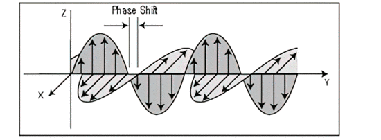
Circularly polarized light is generated when a linear electric field component is out of phase with the orthogonal component by λ/4, as shown in Fig. 1C.
Elliptically polarized light represents an arbitrary phase shift between the two electric field components, as shown in Figure 1D.
We create linearly polarized light when we transmit unpolarized light through a polarizing medium whose axis coincides with the desired linear polarization. When this polarized light is passed through a second polarizer, only the components that are parallel to the polarization axis can emerge, while the orthogonal component is absorbed. When vertically polarized light is sent through a polarizer oriented at 45°, the amplitude of the emerging light decreases by a factor of 1/lambda/2 and the intensity decreases by 50% of the original intensity. When vertically polarized light is sent through a horizontally oriented polarizer, no component of the original light is parallel to the direction of polarization and no light exits.
delay
Another useful tool for manipulating polarized light is the phase retarder. The phase delay is achieved by making the optical path length for one of the orthogonal polarizations different from the other.
Lambda/4 plate
If the orthogonal electric field components are equivalent, a phase shift in one component results in circularly polarized light, as shown in part C of Figure 1. Retarders that cause this shift are called “lamda/4 plates”. They have the unique property of converting elliptically polarized light into linearly polarized light or converting linearly polarized light into circularly polarized light when the fast axis of the quarter wave plate is 45° to the incident plane of polarization. This is done using birefringent, uniaxial materials with two different refractive indices. Light polarized along the direction with the smaller index travels faster and therefore this axis is called the fast axis. The other axis is the slow axis.
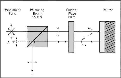
Alignment of Lamda/4 plates is achieved using a linear polarizer and a mirror as shown in Figure 2. Using a polarization beam splitter, vertically polarized light is directed through an Lmada/4 plate onto a mirror. If the angle between the fast axis of the quarter-wave plate and the plane of polarization is 45°, the reflected light has a polarization that is 90° to the polarization of the original source. This maximizes the light at B and minimizes the light at reference point A, as shown in Figure 2.
Lambda/2 plate
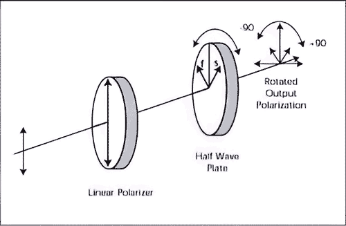
A retarder that produces a λ/2 phase shift is known as a “Lamda/2 plate”. Lambda/2 plates can rotate the polarization of linearly polarized light to twice the angle between the fast axis of the retarder and the plane of polarization. Placing the fast axis of a Lambda/2 plate at 45° to the plane of polarization results in a polarization rotation of 90°.
When circularly polarized light is passed through a half-wave plate, the “handedness” of the polarization changes. This corresponds to shifting the horizontal polarization in Figure C by one λ.
Optical isolators
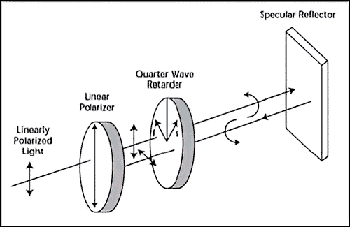
Retarders used in conjunction with Polarizers used provide many useful devices. For example, optical isolation can be achieved by combining a linear polarizer with a lambda/4 plate. By correctly aligning this plate with the linear polarizer, linearly polarized light is converted to circularly polarized light. Since circularly polarized light exhibits a shift in "handedness" when reflected by a mirror, the reflected light is now linearly polarized and rotated 90° with respect to the light leaving the isolator. Horizontally polarized light falling on a vertically aligned polarizer is rejected.
Optical attenuators
An optical attenuator is made by combining two linear Polarizers and a half-wave plate. The input and output polarizers are crossed so that no light passes through them. However, by inserting the half-wave plate, light can pass through the device. The amount of light is determined by the angle between the optical axis of the incident polarizer and the half-wave plate. By placing the optical axis of the half-wave plate at an angle of 45 ° to the incoming polarizer, maximum transmission is achieved. Aligning the optical axis of the half-wave plate with either
The optical axes of the input or output polarizer provide the minimum transmission. How close the minimum is to zero transmission depends on the quality of the Polarizers and the half wave
Plate used in the device.
By replacing the half-wave plate with a device that varies polarization, such as B. a variable delayer, a variable attenuator is created. This configuration is shown in Figure 4. If we align the fast axis of the variable retarder at 45° to the input polarizer and modulate the delay between half-wave and full-wave, the transmission varies between maximum and minimum, creating an optical shutter chopper.

polarization rotator
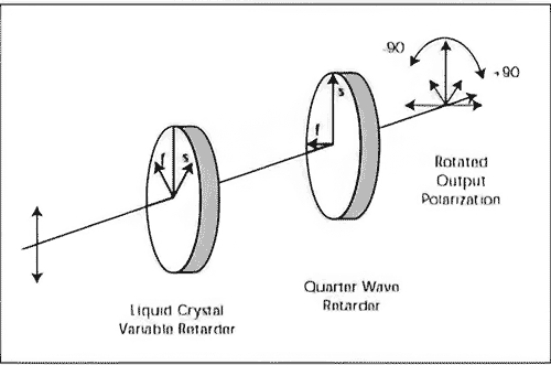
A simple polarization rotator consists of a half-wave plate in linearly polarized light. Rotating the half-wave plate rotates the polarization by twice the angle of the half-wave plate's fast axis with the polarization plane, as shown in Figure 5A. We achieve variable polarization rotation by aligning the fast axis of a variable retarder at 45° to the incoming polarization and following this component with a lambda/4 plate whose slow axis is aligned with the incoming polarization, as shown in Figure 5B. The amount of rotation achieved depends on the amount of deceleration exhibited by the first decelerator. The polarization axis is rotated by an angle that is half the phase shift provided by the variable retarder.
Variable beam splitter
We can create a variable beam splitter by passing linearly polarized light through a half-wave plate in combination with a polarizing beam splitter. The polarization of the light through the beam splitter determines the amount of light that the beam splitter transmits and reflects. By aligning the retarder axis with the vertical input polarization, total reflection through the beam cube is achieved.
Conversely, rotating the fast axis of the half-wave plate through a 45° angle with the input polarization plane ensures full transmission through the beamsplitter. If you replace the half-wave plate with a variable retarder whose fast axis is 45° to the incoming polarization, you get the same beam splitting results as before without mechanical movement. By varying the delay between the 0 and half-wave values, an optical switch is created.
Conclusion
In this application note we have given a basic description of light polarization and some of the tools for controlling the polarization state of light. Retarders and Polarizers have been used in simple devices that enable some of the usual manipulations required wherever light is measured.